
With the Concrete Design add-on, you can perform the fatigue design of members and surfaces according to EN 1992‑1‑1, Chapter 6.8.
For the fatigue design, you can optionally select two methods or design levels in the design configurations:
- Design Level 1: Simplified design according to 6.8.6 and 6.8.7(2): The simplified design is performed for frequent action combinations according to EN 1992‑1‑1, Chapter 6.8.6 (2), and EN 1990, Eq. (6.15b) with the traffic loads relevant in the serviceability state. A maximum stress range according to 6.8.6 is designed for the reinforcing steel. The concrete compressive stress is determined by means of the upper and lower allowable stress according to 6.8.7(2).
- Design Level 2: Design of damage equivalent stress acc. to 6.8.5 and 6.8.7(1) (simplified fatigue design): The design using damage equivalent stress ranges is performed for the fatigue combination according to EN 1992‑1‑1, Chapter 6.8.3, Eq. (6.69) with the specifically defined cyclic action Qfat.

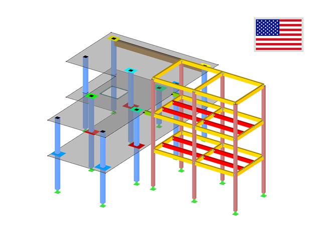
Complex Connection of Horizontal Beams to Column and Connection of Reinforcing Diagonals
The connection model was modeled using about 50 components. The model was created according to the real example of use in structure.

During the cross-section design, you can directly control whether the concrete surface is applied behind the reinforcing bars or is subtracted from the concrete cross-section. You can use the design of the net concrete cross-section especially in the case you deal with a highly reinforced cross-section.
The material library already includes the Canadian types of concrete and reinforcing steel available for design. However, you can always define other materials for the design according to CSA A23.3.
The units used for the reinforced concrete design according to CSA A23.3 are adjusted to the metric system by default.
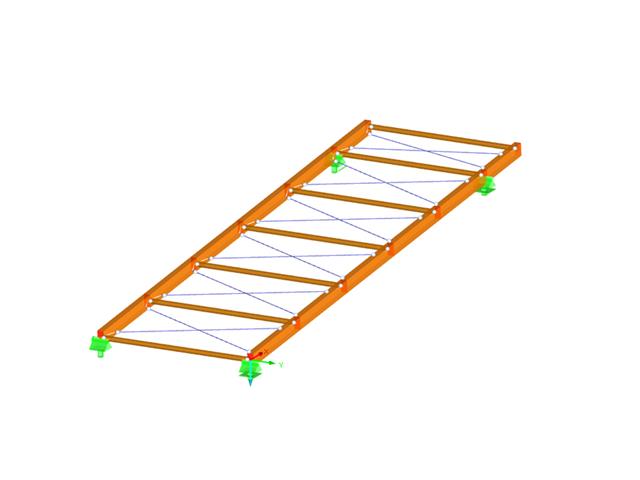
- Design of the following roof types:
- Monopitch roof
- Duopitch Roof
- Curved roof
- All roof shapes allow for a free selection of stiffening diagonals. The following types are available:
- Falling diagonals
- Rising diagonals
- Crossing diagonals with verticals
- Crossing diagonals without verticals
- Crossing diagonals with steel strips (ties)
- Consideration of window rows in the ridge by selecting an inner intermediate part.
- For design according to EC 5 (EN 1995), the following National Annexes are available:
-
 DIN EN 1995-1-1/NA:2013-08 (Germany)
 -
 NBN EN 1995-1-1/ANB:2012-07 (Belgium)
 -
 DK EN 1995-1-1/NA:2011-12 (Denmark)
 -
 SFS EN 1995-1-1/NA:2007-11 (Finland)
 -
 NF EN 1995-1-1/NA:2010-05 (France)
 -
 UNI EN 1995-1-1/NA:2010-09 (Italy)
 -
 NEN EN 1995-1-1/NB:2007-11 (Netherlands)
 -
 ÖNORM B 1995-1-1:2015-06 (Austria)
 -
 PN EN 1995-1-1/NA:2010-09 (Poland)
 -
 SS EN 1995-1-1 (Sweden)
 -
 STN EN 1995-1-1/NA:2008-12 (Slovakia)
 -
 SIST EN 1995-1-1/A101:2006-03 (Slovenia)
 -
 CSN EN 1995-1-1:2007-09 (Czech Republic)
 -
 BS EN 1995-1-1/NA:2009-10 (the United Kingdom)
-
- Simple geometry input with illustrative graphics
- Automatic generation of wind loads
- Automatic creation of required combinations for the ultimate and serviceability limit states, as well as fire resistance design
- Free definition of the load cases to be used
- Extensive material library
- Optional extension of material library by further materials
- Extensive library of permanent loads
- Allocation of framework to service classes and specification of service class categories
- Determination of design ratios, support forces, and deformations
- Info icon indicating successful or failed design
- Color reference scales in result tables
- Direct data export to MS Excel
- DXF interface for preparation production documents in CAD
- Program languages: English, German, Czech, Italian, Spanish, French, Portuguese, Polish, Chinese, Dutch, and Russian
- Verifiable printout report, including all required designs. Printout report available in many output languages; for example, English, German, French, Italian, Spanish, Russian, Czech, Polish, Portuguese, Chinese, and Dutch.
- In the ultimate limit state design, the stiffness of the hinge is divided by the partial safety factor and in the serviceability limit state design calculated using the mean stiffnesses. The limit values for the ultimate and the serviceability limit states can be defined separately.
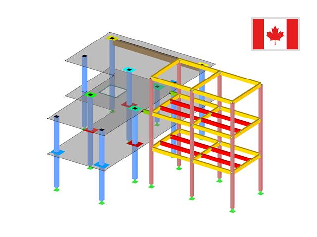
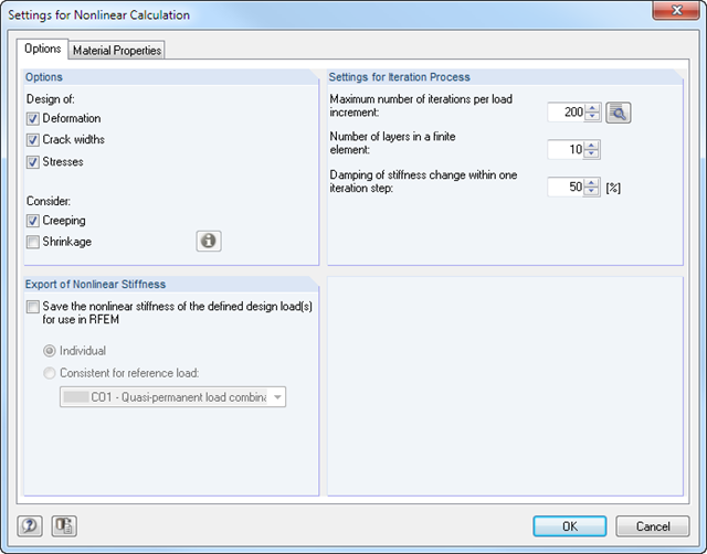
RF-CONCRETE Surfaces
The nonlinear calculation is activated by selecting the design method of the serviceability limit state. You can individually select the analyses to be performed as well as the stress-strain diagrams for concrete and reinforcing steel. The iteration process can be influenced by these control parameters: convergence accuracy, maximum number of iterations, arrangement of layers over cross-section depth, and damping factor.
You can set the limit values in the serviceability limit state individually for each surface or surface group. Allowable limit values are defined by the maximum deformation, the maximum stresses, or the maximum crack widths. The definition of the maximum deformation requires additional specification as to whether the non-deformed or the deformed system should be used for the design.
RF-CONCRETE Members
The nonlinear calculation can be applied to the ultimate and the serviceability limit state designs. In addition, you can specify the concrete tensile strength or the tension stiffening between the cracks. The iteration process can be influenced by these control parameters: convergence accuracy, maximum number of iterations, and damping factor.
- Cross-section modeling using surfaces, openings, and point areas (reinforcements) limited by polygons
- Automatic or individual arrangement of stress points
- Extensible library of concrete, steel, and reinforcing steel materials
- Cross-section properties of reinforced concrete and composite cross-sections
- Stress analysis with yield hypothesis according to von Mises and Tresca
- Reinforced concrete design according to:
-
DIN 1045-1:2008-08
-
DIN 1045:1988-07
-
ÖNORM B 4700: 2001-06-01
-
 EN 1992-1-1:2004
-
- For the design according to EN 1992-1-1:2004, the following National Annexes are available:
-
DIN EN 1992-1-1/NA:2013-04 (Germany)
-
NEN-EN 1992-1-1/NA:2011-11 (Netherlands)
-
CSN EN 1992-1-1/NA:2006-11 (Czech Republic)
-
ÖNORM B 1992-1-1:2011-12 (Austria)
-
 UNE EN 1992-1-1/NA:2010-11 (Spain)
 -
EN 1992-1-1 DK NA:2007-11 (Denmark)
-
SIST EN 1992-1-1:2005/A101:2006 (Slovenia)
-
NF EN 1992-1-1/NA:2007-03 (France)
-
STN EN 1992-1-1/NA:2008-06 (Slovakia)
-
SFS EN 1992-1-1/NA:2007-10 (Finland)
-
BS EN 1992-1-1:2004 (United Kingdom)
-
 SS EN 1992-1-1/NA:2008-06 (Singapore)
 -
 NP EN 1992-1-1/NA:2010-02 (Portugal)
 -
UNI EN 1992-1-1/NA:2007-07 (Italy)
-
SS EN 1992-1-1/NA:2008 (Sweden)
-
PN EN 1992-1-1/NA:2008-04 (Poland)
-
NBN EN 1992-1-1 ANB:2010 (Belgium)
-
 NA to CYS EN 1992-1-1:2004/NA:2009 (Cyprus)
 -
 BDS EN 1992-1-1:2005/NA:2011 (Bulgaria)
 -
 LST EN 1992-1-1:2005/NA:2011 (Lithuania)
 -
 SR EN 1992-1-1:2004/NA:2008 (Romania)
-
- In addition to the National Annexes (NA) listed above, you can also define a specific NA, applying user‑defined limit values and parameters.
- Reinforced concrete design for stress-strain distribution, available safety, or direct design
- Results of reinforcement list and total reinforcement area
- Printout report with option to print a short form
The material library already includes the American types of concrete and reinforcing steel available for design. However, you can always define other materials for the design according to ACI 318.
By default, the units that are used for the reinforced concrete design according to ACI 318 are set to the imperial system of measurement.
RF-CONCRETE Surfaces:
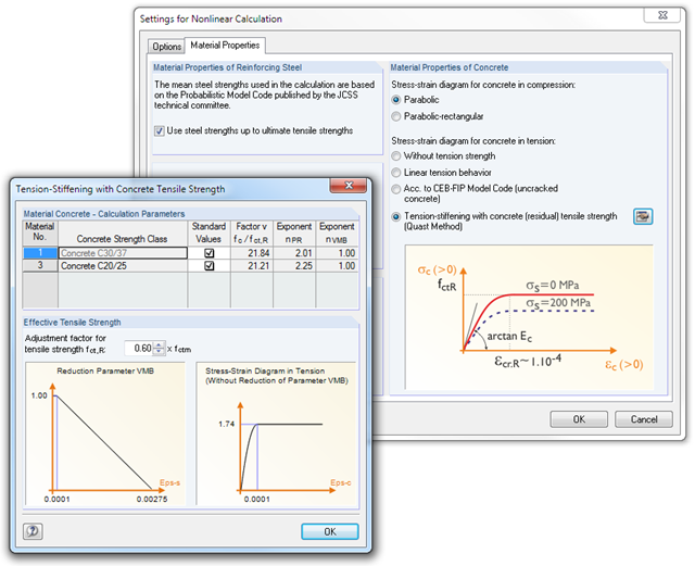
The nonlinear deformation analysis is performed by an iterative process considering the stiffness in cracked and non-cracked sections. The nonlinear reinforced concrete modeling requires definition of material properties varying across the surface thickness. Therefore, a finite element is divided into a certain number of steel and concrete layers in order to determine the cross-section depth.
The mean steel strengths used in the calculation are based on the 'Probabilistic Model Code' published by the JCSS technical committee. It is up to the user whether the steel strength is applied up to the ultimate tensile strength (increasing branch in the plastic area). Regarding material properties, it is possible to control the stress-strain diagram of the compressive and tensile strength. For the concrete compressive strength, you can select a parabolic or a parabolic-rectangular stress-strain diagram. On the tension side of the concrete, it is possible to deactivate the tensile strength as well as to apply a linear-elastic diagram, a diagram according to the CEB-FIB model code 90:1993, and concrete residual tensile strength considering the tension stiffening between the cracks.
Furthermore, you can specify which result values should be displayed after the nonlinear calculation at the serviceability limit state:
- Deformations (global, local based on non-/deformed system)
- Crack widths, depths, and spacing of the top and bottom sides in principal directions I and II
- Stresses of the concrete (stress and strain in principal direction I and II) and of the reinforcement (strain, area, profile, cover, and direction in each reinforcement direction)
RF-CONCRETE Members:
The nonlinear deformation analysis of beam structures is performed by an iterative process considering the stiffness in cracked and non-cracked sections. The material properties of concrete and reinforcing steel used in the nonlinear calculation are selected according to a limit state. The contribution of the concrete tensile strength between the cracks (tension stiffening) can be applied either by means of a modified stress-strain diagram of the reinforcing steel, or by applying a residual concrete tensile strength.
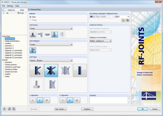
- Wide range of joint types, for example:
- Bolted connection of diagonals without gusset plate 2D
- Bolted connection of diagonals without gusset plate 3D
- Bolted column joint
- T-, K-, and KT-joints considered for connections of diagonals
- Various categories of connections:
- A - shear/hole bearing connection
- B - slip-resistant connection at serviceability limit state
- C - slip-resistant connection at ultimate limit state
- Bolt strength classes of 4.6 - 10.9
- Bolt diameters M12 - M42
- Modifiable bolt spacing
- Visualization of the entire connection in the view window
The material library already includes German types of concrete and reinforcing steel available for design. However, you can always define other materials for the design according to DIN 1045‑1.
- Iterative nonlinear calculation of deformations for beam and plate structures consisting of reinforced concrete by determining the respective element stiffness subjected to the defined loads
- Deformation analyses of cracked reinforced concrete surfaces (state II)
- General nonlinear stability analysis of compression members made of reinforced concrete; for example, according to EN 1992-1-1, 5.8.6
- Tension stiffening of concrete applied between cracks
- Numerous National Annexes available for the design according to Eurocode 2 (EN 1992-1-1:2004 + A1:2014, see EC2 for RFEM)
- Optional consideration of long-term influences such as creep or shrinkage
- Nonlinear calculation of stresses in reinforcing steel and concrete
- Nonlinear calculation of crack widths
- Flexibility due to detailed setting options for basis and extent of calculations
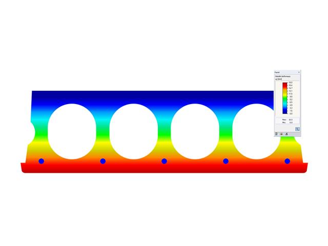
- Graphical representation of results integrated in RFEM; for example, deformation or sag of a flat slab made of reinforced concrete
- Numerical results clearly arranged in tables and graphical display of the results in the model
- Complete integration of results in the RFEM printout report
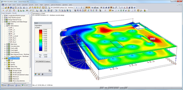
After the calculation, the module shows clearly arranged tables listing the results of the nonlinear calculation. All intermediate values are included in a comprehensible manner. Graphical representation of design ratios, deformations, concrete and reinforcing steel stresses, crack widths, crack depths, and crack spacing in RFEM facilitates a quick overview of critical or cracked areas.
Error messages or remarks concerning the calculation help you find design problems. Since the design results are displayed by surface or by point including all intermediate results, you can retrace all details of the calculation.
Due to the optional export of input or result tables to MS Excel, the data remain available for further use in other programs. The complete integration of results in the RFEM printout report guarantees verifiable structural design.
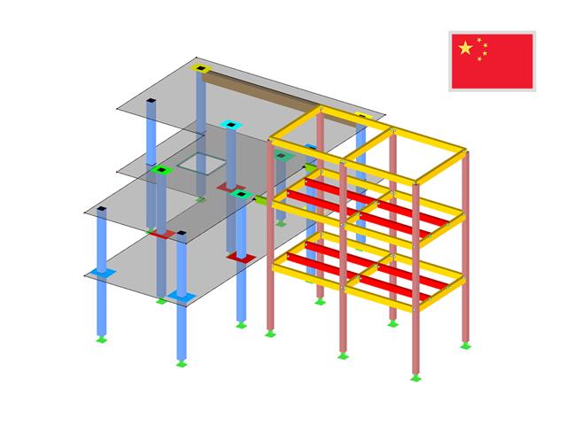
The material library already includes the Chinese types of concrete and reinforcing steel available for design. However, you can always define other materials for the design according to GB 50010.
In addition, it is possible consider the seismic design according to the standard GB 50011‑2010 (Code for seismic design of buildings).
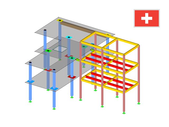
The material library already includes Swiss types of concrete and reinforcing steel available for design. However, you can always define other materials for the design according to SIA 262. The program performs the ultimate and the serviceability limit state design.
The crack width analysis can be performed using the design of Sigmas,adm, rebar spacing sL, or a direct calculation of crack widths according to the technical documentation D0182. Depending on the selected concrete type, the program determines the limit value Sigmas,adm according to D0182, Eq. 10.13; the upper limit is set by the design criterion fsd.